This procedure assumes you
have multiple devices that support DD-WRT software. These might include the
Lynksys WRT54GL or Buffalo WHR-HP-G54 and others but the buffalo model is higher
power and more sensitive and therefore more effective. It has about 400mW of
actual RF output power and contains an RF preamp to help it pick up much weaker
signals. Its performance is within 4db of the most expensive Value Point indoor
and outdoor 1 watt routers used commercially in hotels and municipalities.
The Buffalo WHR-HP-G54 is available at Newegg.com for a reasonable price. They
must be loaded with the open source DD-WRT V24 pre SP-2 from the dd-wrt.com
website. Get a copy right HERE.
They should be reset to the factory default state by pushing and holding the
reset button for at least 10 seconds or from the administration page.
In any of these
systems a computer can be connected wirelessly or directly to any of the four
ports of any router and be able to access the internet. The Santa Rosa stake has
6 buildings and 5 of them have completely wireles networks with either Linksys
wireless cards in the clerks offices computers or if one of the wireless
repeater access points or head end is near by like we have at two of the
buildings then a LAN cable can be connected to one of the four ports. If
desired, additional buffalo routers can be used as wireless bridges. Reliability
is excellent in all these systems and the internet can be accessed throughout
all buildings in the stake.
A typical setup might include three access points. One located in the utility room entry point where the phone panel is located, or in a clerk’s office. A second access point would be placed in another clerk’s office or any other room on the opposite side of the chapel. If it’s in the clerk’s office it could be plugged into the computer thus saving the need for a wireless card. A third unit could be placed in a furnace room somewhere near the back of the cultural hall. These can then be wirelessly connected to the first.
Here are two configurations:

Yulupa Building
Stony Point
Stony Point
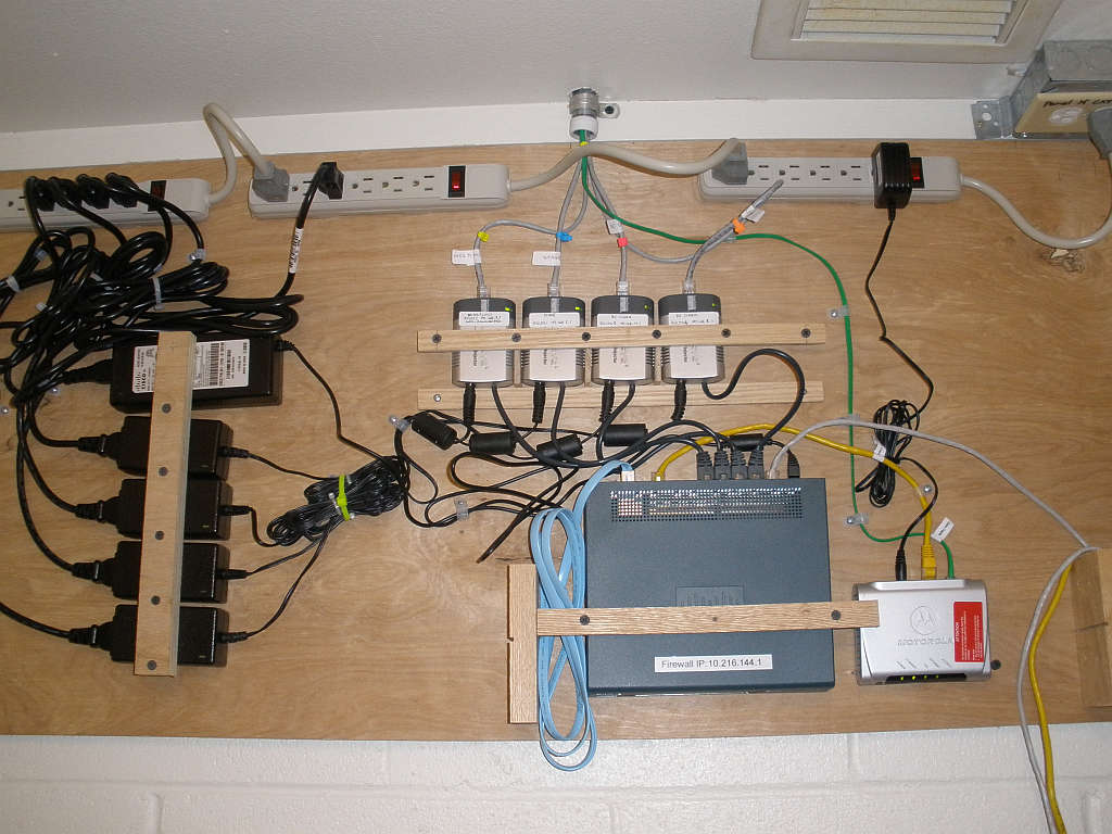
Badger Lane. This is an example of a wired system with 4 48V POE injectors for powering each access point.
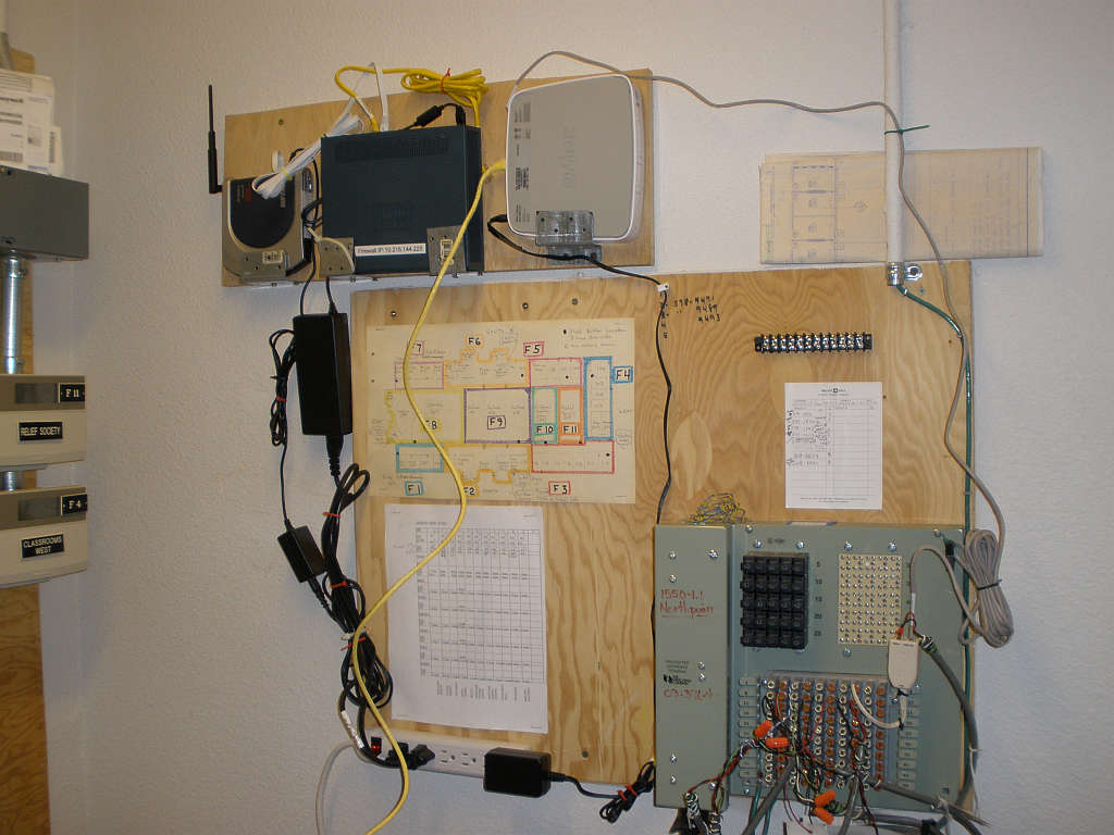
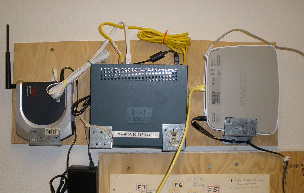
These setups are located in the utility room where the phone lines come into the building. The 2wire router's wireless capability has been disabled and the Buffalo high power router with the DD-WRT software is connected after the church firewall. The second photo shows the phone panel and you can see a DSL splitter that's wired so that the line coming in splits to the DSL modem and bishops office.
In a wired system each device is configured as a bridge. The WAN connection type is disabled and is not used. One of the 4 ports will be connected to the firewall. The local IP address for each wireless device will need to be different but don't need to be on the same subnet as the firewall. They should be set to 192.168.1.200 for router #1 then 192.168.1.201 for router #2 an so on but not 192.168.1.1 as shown in the example below, as this may conflict with the DSL modem in some cases. The gateway must be set to the IP address on the church firewall. The DHCP server should be disabled. All DHCP services will come from the church managed firewall. The SSID's should all be the same for a wired system. The configuration page for each can be reached from anywhere in the system.
More information about How to Build a Wireless Bridge Using DD-WRT can be found HERE
Each wireless router should be set to the same channel.
If the same SSID is used for each then as a PC is moved around it will switch to the strongest one
Nothing special here.
Here are the proper time settings for the routers internal clock in the bottom of the setup menu.
This will allow the routers to keep bandwidth usage reports..
Once up and running, the configuration pages of all the routers can then be accessed wirelessly by setting the PC wireless card for a manual IP address of something like 192.168.1.10 and not to DHCP. See example below. When connected to any one of the wireless access points in the system the configuration pages of any other wireless router comes up by typing it's IP address into the web browser. For normal use of the system though, it should be set to automatic. The PC will then receive an IP address from the church firewall and work on the internet as normal but can no longer connect to any of the configuration pages.
Testing so for shows that a WDS linked system is almost the same as the wired system. The DHCP server will still be the church managed firewall. there can only be one DHCP server on the system. It does not work until the SSID's are set all the same so in the test they were all set to "LDS 1". Only the addition of a WDS node on each router was added in addition to the other settings. No LAN cable was present on wireless router 2. Computers can be connected with LAN cables directly to any of the wireless routers in the system and they will receive DHCP services from the church managed firewall and work perfectly. Further QA testing of the DD-WRT app is needed. Not tested are wireless router 3 which should be linked to wireless router 1 also, and could a forth unit be connected to the third in a daisy chain.
Before adding the WDS nodes, all other settings in the main setup page, wireless, and wireless security should first be established as shown above. On each router, you will see its wireless MAC address at the top of the Wireless -> WDS page. Put each router's MAC into the table of the other router it connects to, and select LAN for the type. Note that this MAC address is different from the one that may be printed on your case!
Here are more instructions on configuring DD-WRT Routers in a WDS connected router network.
In this type of system the SSID for each access point must differ. The configuration page can only be reached on the unit you are connected to. IP subnets for router #2 and #3 can be the same but must differ from #1 when they are both connected to number 1. A repeater's subnet must differ from what it's connected to.
1: login to newly factory defaulted router. Usualy http://192.168.1.1
2: Set user name and password. Something like User = root and password = ab7k9r
3: Go to Setup and change the Local IP Address to 192.168.3.1 The Subnet Mask will default to 255.255.255.0 then press save.
4: Set time zone to UTC -8, DST Last Sunday March, Server 2.us.pool.ntp.org then press save.
5: Cycle power.
6: Wait for new DHCP to come up on computer then login to router. Now http://192.168.3.1
7: In Wireless settings, set Wireless Mode to repeater then apply. Next select add under virtual interface and set it's SSID to something like LDS 2 then save.
8: Now select Status then Wireless and then at bottom select Site Survey. A list of neighbors wireless networks will be shown. Select one and press join. This will grab the MAC address and SSID and add it to the wireless physical interface in the wireless tab and it will connect it to that network.
9. Select Wireless and security. Set both the Physical and Virtual interfaces to WPA Personal then Enter the WPA shared key you will be using on the wireless network something like "1LDS1830" and press save.


This batch file is usefull for flashing the dd-wrt firmware onto a new buffalo WHR-HP-G54 router.
@echo off
echo ============================================================================
echo Type or paste the firmware filename below and then press Enter.
echo.
set /p dd-wrt_fn=Firmware Filename:
echo.
if not exist %dd-wrt_fn% goto FNF_ERROR
echo ============================================================================
echo This batch file will upload %dd-wrt_fn% in the current
echo directory to 192.168.11.1 during the router's bootup.
echo.
echo * Set your ethernet card's settings to:
echo IP: 192.168.11.2
echo Mask: 255.255.255.0
echo Gateway: 192.168.11.1.
echo * Unplug the router's power cable.
echo.
echo Press Ctrl+C to abort or any other key to continue . . .
pause > nul
echo.
echo * Re-plug the router's power cable.
echo.
echo ============================================================================
echo Waiting for the router; Press Ctrl+C to abort . . .
echo.
:PING
ping -n 1 -w 50 192.168.11.1 > nul
if errorlevel 1 goto PING
echo tftp -i 192.168.11.1 put %dd-wrt_fn%
tftp -i 192.168.11.1 put %dd-wrt_fn%
if errorlevel 1 goto PING
echo.
echo ============================================================================
echo * WAIT for about 2 minutes while the firmware is being flashed.
echo * Reset your ethernet card's settings back to DHCP.
echo * The default router address will be at 192.168.11.1.
echo.
pause
goto END
:FNF_ERROR
echo ============================================================================
echo ERROR: Make sure this batch file and the firmware are in the same directory!
echo.
pause
:END
Download Latest DD-WRT HERE
A usefull tool on these routers is the info page that comes up when you first go to the routers IP address. It shows the signal strength off all the connections. Testing has shown this needs to be 23% or higher to get reliable operation. Below is an example of 30% and 40% which are both good.